今回はTeXを用いた電気回路図の作成のうちOPアンプ、スイッチの表示について紹介したい。
1. OPアンプ
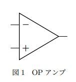
OPアンプ単体を表示するにはnode[op amp]とする。
\begin{figure}
\begin{center}
\begin{circuitikz}
\draw (0,0) node[op amp] {};
\end{circuitikz}
\caption{OPアンプ}
\end{center}
\end{figure}
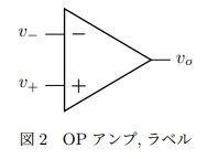
OPアンプの入力、出力にラベルを表示するには、OPアンプの入力、出力の座標に表示したい文字を挿入する。
OPアンプの入力の座標はプラス側:(,+),マイナス側:(.-), 出力側:(.out)で取得できる。
例えば、OPアンプの名称をopampとして、(opamp.+) node[left] {$v_+$}とすれば入力左側にv+のラベルが表示される。
\begin{figure}
\begin{center}
\begin{circuitikz}
\draw (0,0) node[op amp] (opamp) {}
(opamp.+) node[left] {$v_+$}
(opamp.-) node[left] {$v_-$}
(opamp.out) node[right] {$v_o$};
\end{circuitikz}
\caption{OPアンプ,ラベル}
\end{center}
\end{figure}
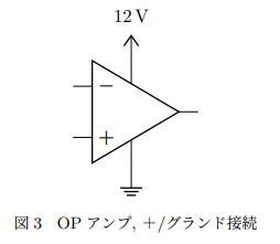
OPアンプの電源供給を表示するには、座標(.up)と(.down)を用いる。例えば+電圧と接続したければ、(.up)から適当な距離(0,0.5)をインクリメントして、node[vcc]に接続する。
\begin{figure}
\begin{center}
\begin{circuitikz} \draw
(0,0) node[op amp] (opamp) {}
(opamp.up) --++(0,0.5) node[vcc]{12\,\textnormal{V}}
(opamp.down) --++(0,-0.5) node[ground]{};
\end{circuitikz}
\caption{OPアンプ, +/グランド接続}
\end{center}
\end{figure}
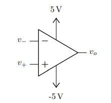
\begin{figure}
\begin{center}
\begin{circuitikz} \draw
(0,0) node[op amp] (opamp) {}
(opamp.+) node[left] {$v_+$}
(opamp.-) node[left] {$v_-$}
(opamp.out) node[right] {$v_o$}
(opamp.up) --++(0,0.5) node[vcc]{5\,\textnormal{V}}
(opamp.down) --++(0,-0.5) node[vee]{-5\,\textnormal{V}};
\end{circuitikz}
\caption{OPアンプ ±接続}
\end{center}
\end{figure}
2. OPアンプ応用回路
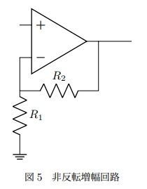
OPアンプの応用として非反転増幅回路を表示する。まずデフォルトのOPアンプの入力は+が下、-が上になっているが、noinv input upをオプション指定することで上下入れ替えることができる。-入力側、線を垂直方向に抵抗R1、グランドを描画するには(opamp.-) -- ++(0,-1) to [R=$R_1$] ++ (0,-1.5) node[ground]{}となるが、抵抗の接続点座標を後で再利用するためcoordinate(BR)として座標の固有名を与えておく。
次にR1の接続点から抵抗R2とOPアンプ出力を接続する。R1の接続点とOPアンプの出力座標の交点を指定する便利な方法として(BR -| opamp.out)とするだけでよい。
R1の接続点から抵抗R2、OPアンプの出力座標の交点、OPアンプの出力座標を描画は
(BR) to [R=$R_2$] (BR -| opamp.out) -- (opamp.out) -- ++(1,0)となる。最後の++(1,0)はOPアンプの出力を少し伸ばすために入れた。
\begin{figure}
\begin{center}
\begin{circuitikz}
\draw (0,0) node[op amp, noinv input up] (opamp){}
(opamp.-) -- ++(0,-1) coordinate(BR) to [R=$R_1$] ++(0,-1.5) node[ground]{}
(BR) to [R=$R_2$]  (BR -| opamp.out) -- (opamp.out) -- ++(1,0) ;
\end{circuitikz}
\caption{非反転増幅回路}
\end{center}
\end{figure}
3. スイッチ
スイッチは開閉の矢印つきのものは閉じる方向のものでspstまたはcspst、開く方向のものはospstを用いる。
また矢印なしの場合はostを用いる。
\begin{figure}
\begin{center}
\begin{circuitikz}
\draw (0,0) [spst] to ++(1,0);
\draw (0,-1) [cspst] to ++(1,0);
\draw (0,-2) [ospst] to ++(1,0);
\draw (0,-3) [nos] to ++(1,0);
\end{circuitikz}
\caption{スイッチ}
\end{center}
\end{figure}

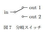
2分岐スイッチはnode[spdt]を用いる。それぞれラベルを付けるには、入力側は.in, 分岐出力側は,out 1, .out 2で座標を取得することができる。
\begin{figure}
\begin{center}
\begin{circuitikz}
\draw (0,0) node[spdt](Sw) {}
(Sw.in) node[left] {in}
(Sw.out 1) node[right] {out 1}
(Sw.out 2) node[right] {out 2};
\end{circuitikz}
\caption{分岐スイッチ}
\end{center}
\end{figure}
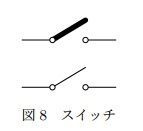
スイッチにノード(白丸)を表示したい場合、Cute Switch: coswを利用する。デフォルトはスイッチ部分の線が太いので\ctikzset{bipoles/cuteswitch/thickness=0.2}としてCute Switchの線幅を変更することで、回路図でよくみかける形式になる。
\begin{figure}
\begin{center}
\begin{circuitikz}
\draw (0,0) [cosw] to ++(2,0);
\ctikzset{bipoles/cuteswitch/thickness=0.2}
\draw (0,-1) [cosw] to ++(2,0);
\end{circuitikz}
\caption{ノード付きスイッチ}
\end{center}
\end{figure}
4 まとめ
今回はOPアンプの表示とラベルの付け方、入出力の座標取得、またスイッチの表示について紹介した。