Texによる文書作成43 ~電気回路の作図13
今回はTeXを用いた電気回路図の作成のうち、コネクタ、ロジックゲートの表示について紹介したい。
1. BNCコネクタ
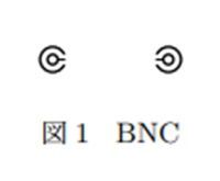
BNCコネクタを表示するには、node[bnc]とする。名前はBNCだがSMAなど他の同軸コネクタの代用としてもよいかもしれない。
\begin{figure}
\begin{center}
\begin{circuitikz}
\draw (0,0) node[bnc]{};
\draw (1,0) node[bnc, xscale=-1]{};
\end{circuitikz}
\caption{BNC}
\end{center}
\end{figure}
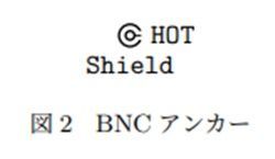
アンカーを用いてBNCコネクターの信号線の位置を.hot, シールド線を.shieldとして指定することができる。
\begin{figure}
\begin{center}
\begin{circuitikz}
\draw (0,0) node[bnc](B){}
(B.hot) node[right] {\texttt{HOT}}
(B.shield) node[below] {\texttt{Shield}};
\end{circuitikz}
\caption{BNCアンカー}
\end{center}
\end{figure}
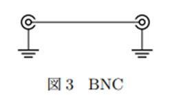
アンカーを用いてBNCコネクターの信号線同士を接続し、シールド線をグランドに接続した例を以下に示す。
\begin{figure}
\begin{center}
\begin{circuitikz}
\draw (0,0) node[bnc](B1){};
\draw (2,0) node[bnc, xscale=-1](B2){};
\draw (B1.hot) -- (B2.hot);
\node [ground] at (B1.shield) {};
\node [ground] at (B2.shield) {};
\end{circuitikz}
\caption{BNC}
\end{center}
\end{figure}
2. ロジックゲート
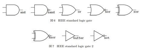
ロジックゲートのうちAND回路はnode[american and port]として表示できる。andの部分をnand, or, nor,xor,xnor,buffer,notに変更すれば、それぞれの回路が表示される。またamericanの部分をieeestdに置き換えるとIEEE Standard形式のロジックゲートが表示される。
アンカーは入力部は.in 1,.in 2, 出力部は.outで指定できる。
\begin{figure}
\begin{center}
\begin{circuitikz}
\draw (0,0) node[american and port](A1){}
(A1.in 1) node[left] {\texttt{in 1}}
(A1.in 2) node[left] {\texttt{in 2}}
(A1.out) node[above] {\texttt{out}};
(A1.out) node[below] {\texttt{and}};
\draw (2,0) node[american nand port](A2){}
(A2.out) node[below] {\texttt{nand}};
\draw (4,0) node[american nor port](A3){}
(A3.out) node[below] {\texttt{nor}};
\draw (6,0) node[american xor port](A4){}
(A4.out) node[below] {\texttt{xor}};
\draw (8,0) node[american xnor port](A5){}
(A5.out) node[below] {\texttt{xnor}};
\draw (9.5,0) node[american buffer port](A6){}
(A6.out) node[below] {\texttt{buffer}};
\draw (11.5,0) node[american not port](A7){}
(A7.out) node[below] {\texttt{not}};
\end{circuitikz}
\caption{American logic gate}
\end{center}
\end{figure}

3. まとめ
今回はBNCコネクタとロジックゲートの表示方法について紹介した。